
Peavey Butcher Adjustable Bias and Service Guide
The contents of this guide in its entirety including schematics can be downloaded here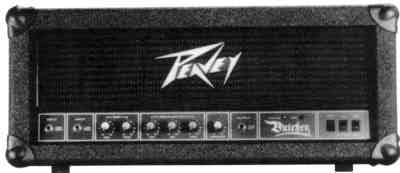
Parts List
Parts list for the bias mod:
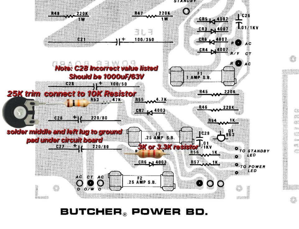
- Piher 25K trim pot
- 3.3K 1/2W resistor
- 10K 1/2W resistor
Parts list for the recap (all axial leads, values updated for modern availability):
| Power Board | Preamp Board | Output Board |
|---|---|---|
| 4 x 100uF / 350V | 4 x 22uF / 450V | 1 x 100uF / 50V |
| 1 x 1000uF / 63V | 1 x 22uF / 50V | |
| 2 x 220uF / 100V |
Adjustable Bias Mod
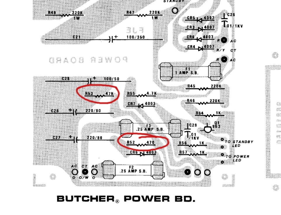
The Butcher came from the factory with a fixed bias supply and no adjustment. R53 (47K) and R52 (470 ohm) are the two resistors we will be working with on the power board.
Notes: From the top view, solder the end of the 10K resistor to the right leg of the trimpot. The middle and left lugs must be soldered to the ground pad on the underside of the board.
The amplifier is over 35 years old and is due for new electrolytic capacitors. It is a very simple job to replace them all and I highly recommend taking this action now — you will likely have another 40 years without any major trouble.
Death Caps!!!
A note on death caps: C30 is what we call a “DEATH CAP”. The reason being is because through the polarity switch, the cap provides a path to chassis ground from either the HOT or NEUTRAL wires from the power cord. In the event that this capacitor ever fails and develops a short it will electrify the chassis with 120VAC wall voltage!!!
The chassis ground is also connected to the ground wire and shield of your instrument cable which could also mean you can become electrocuted by touching your strings.
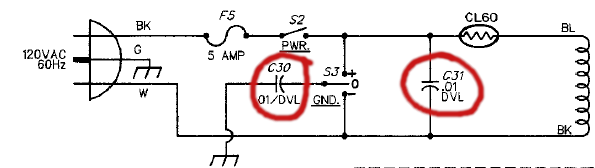
All you need to do is remove C30 and C31 from the terminal strip and you can remove the blue, red, and white wires from the polarity switch entirely. C31 is an across-the-line cap and not a death cap, however, it is still not necessary in the circuit. The black component is an in-rush current limiter and poses no risk. If you do not wish to remove the wires from the polarity switch, simply wire them to ground or an unused part of the terminal strip.
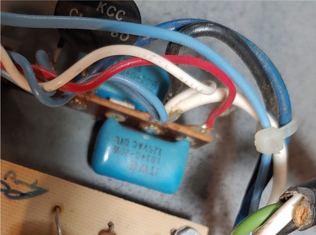
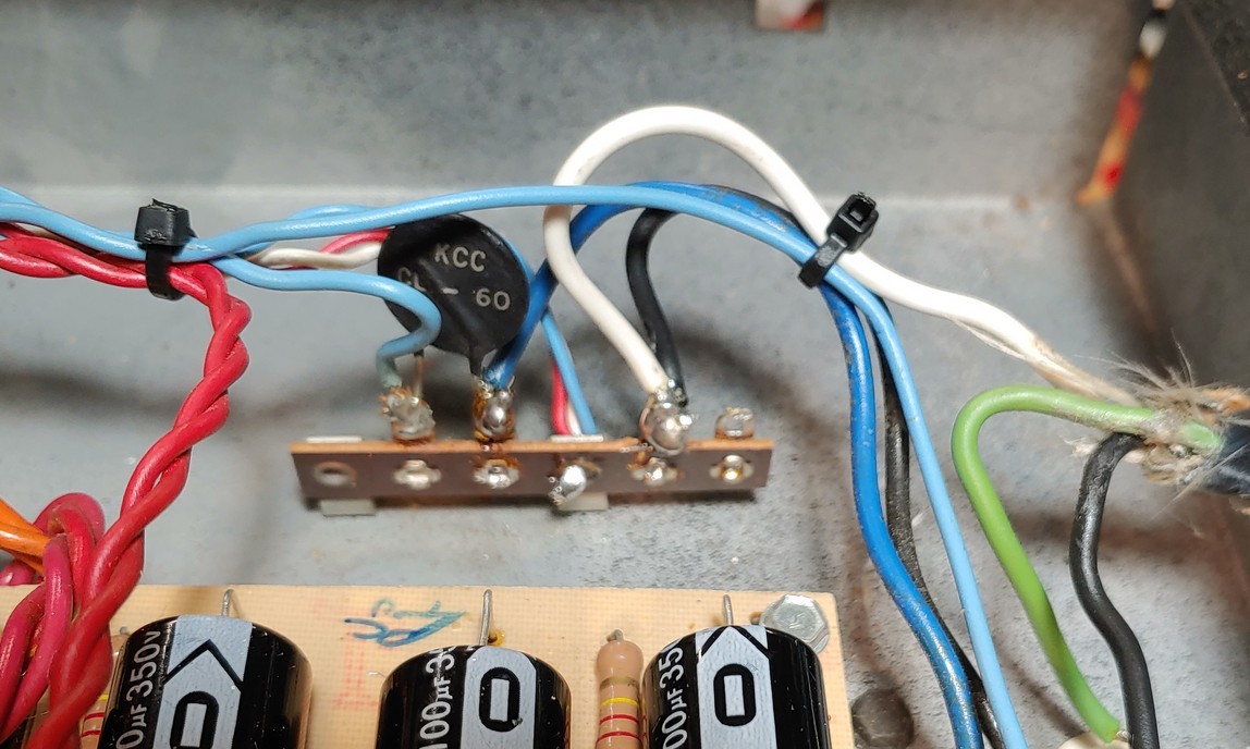
Across-the-line and hot/neutral-to-ground capacitors can be found in other circuits to reduce EMI but they must be rated for the specific application via an X or Y safety capacitor. I don’t believe they provide enough benefit to warrant having them in a guitar amplifier though. Either way, remove the death cap.
Owner’s Manual
The following is the text of the original 1985 Peavey Butcher operating guide.
The Peavey Butcher® has been designed to faithfully reproduce the searing “crunchy” sound sought after by today’s demanding hard-rock guitarists. All controls and functions have been specifically tailored to produce the ultimate in tonality, distortion, and sustain characteristics.
The Butcher will deliver 120 watts RMS into load impedances of 4, 8 or 16 ohms, and is capable of driving multiple enclosures for those players wishing to achieve truly overwhelming sound pressure levels. The cabinet is constructed of 3/4″ wood and is covered with the heaviest available 34 oz. Tolex™. Ruggedness is enhanced by huge metal corners and a steel-reinforced carrying handle.
Internally, the Butcher features chassis construction of 18 gauge steel, massive steel-mounted transformers, and the finest components available. The all-tube circuit utilizes time-tested European ECC-83/12AX7A preamp tubes and proven premium STR6L6GC output tubes.
Controls and Functions
- Power On/Off Switch — A simple two-position switch which controls AC power to the amplifier.
- Standby/On Switch — Allows the amplifier to be placed in standby or active mode.
- Ground Lift Switch — A three-position type with the center (0) position completely removing the internal grounding capacitor from the circuit. When only two-wire service is available, the plus (+) and minus (-) positions may be used to properly ground the amplifier — one will yield the lowest hum. Not operational on 220/240V export models.
- Booster Output — Provides a line-level (1V RMS) signal for driving additional power amplifiers. The signal is taken from the output transformer, so all amplification processing (including the tube power amp) is reflected in it.
- System Presence — Adjusts very high frequencies (5 kHz and above). It occurs after the EQ controls (post-EQ) and is active, so it can boost high-frequency signals and allows fine tuning of tonality, particularly in distorted mode.
- Equalization — Three bands of passive EQ (Low, Mid, High). Because the EQ is passive, it is recommended that one or more controls be operated above minimum; with all EQ controls at minimum the stage is in effect cutting all frequencies. Peavey deliberately limited the Low EQ control, since extreme bass boost consumes disproportionate power at the expense of mids and highs.
- Gain Controls — Pre and Post Gain are normally used together to determine distortion and volume. For distortion, use the High Gain input: Post Gain at about 2, Pre Gain at about 8, then adjust to taste. For clean sounds, use the Low Gain input with the reverse approach.
- Inputs — Two inputs with a significant level difference (32 dB). They cannot be used simultaneously; plugging into the Low Gain input decouples the High Gain input and its extra gain stage from the preamp.
Rear Panel
- Line Cord — A three-wire cord and plug for your safety. Do not remove the ground pin under any circumstances; use a grounding adapter when only two-wire service is available.
- Fuse — Located within the cap of the fuseholder. It must be replaced with a fuse of the same type and value, and only after the line cord has been disconnected from the mains.
- Speaker Jacks — Four jacks delivering 120 watts RMS into 4, 8, or 16 ohms. With a single enclosure, use the jack whose impedance (listed below the jacks) matches the enclosure. With more than one 16 ohm enclosure, follow the listings above the jacks. Never operate the amp into a total load of less than four ohms, and never operate a tube amp without a load attached.
- Hum Balance Control — Minimizes hum from the tube filaments. With the Power switch on and nothing plugged in, set Pre and Post Gain at 10, Low and Mid EQ at 10, High EQ and Presence at 0, then slowly rotate the Hum Balance control until the hum virtually disappears. Adjust monthly, and always after installing new tubes.
Specifications
| Power Amp | Four 6L6GC tubes with 12AX7 driver. 120W RMS into 4, 8 or 16 ohms; 130W RMS at clipping (typically 5% THD, 1 kHz, 120 VAC line — bias must be reduced to measure). Frequency response +0/-2 dB, 50 Hz to 10 kHz at 100W into 16 ohms. Hum & noise greater than 88 dB below rated power. Power consumption 300W, 50/60 Hz, 120 VAC (domestic). |
|---|---|
| Preamp | Two 12AX7 tubes. Specs measured at 1 kHz with Post Gain 10, Low & High EQ 10, Mid EQ 0, Presence 0. |
| High Gain Input | Very High Z, 1M ohm. Nominal -42 dBV (8 mV RMS), minimum -54 dBV (2 mV RMS), maximum -6 dBV (0.5V RMS). Primarily a distortion input. |
| Low Gain Input | Very High Z, 1M ohm. Nominal -10 dBV (300 mV RMS), minimum -22 dBV (80 mV RMS), maximum unlimited. Primarily a non-distortion input. |
| Line Output | Load impedance 10K ohms or greater. Nominal output +6 dBV (2V RMS). |
| EQ & Presence | Special Low, Mid and High passive-type EQ. Presence: +6 dB at 5 kHz. |
| Hum & Noise | System hum and noise at nominal input level (20 Hz–20 kHz unweighted): greater than 78 dB below rated power. |
Peavey Electronics Corp., 711 A Street, Meridian, MS 39301 — printed in U.S.A. ©1985, #80300228 10/85.
Schematics
The original 1985 Peavey factory schematic and circuit board layouts. Click any drawing to enlarge it.
© Purgasound 2026 · www.purgasound.com