
The Ultimate SL-X Guide!
The contents of this guide in its entirety including schematics can be downloaded here
So you’ve decided to work on the SL-X….
The intent of this guide is to provide you with an easy, no-drill solution to the known issue with the DC heater circuit as well as update the amp for years of trouble free service. The SL-X may look complicated compared to its predecessors but the more we can break down and compartmentalize the circuit, the easier it will be to understand. If you are unfamiliar with these specific amplifiers or new to tube amp maintenance or amplifier service in general, please read the entire guide. For the purposes of providing these amplifiers with the longest service life possible we will focus on three key points.
1. Repairing the DC Heating Circuit
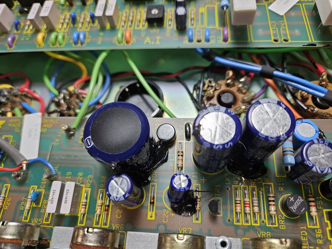
The filaments in the first three preamp tubes in this amplifier use DC as opposed to AC for operation with less noise. This is among one of the most basic DC heater circuits. It achieves this by having AC enter a diode bridge rectifier which exits as DC and is smoothed with a large value, low voltage capacitor. The reason this specific circuit consistently fails is that the rectifier is not rated properly and gets too hot, eventually burns the PCB and the circuit traces underneath it. The excess heat also takes out the C8 smoothing capacitor along with it. Take a look at any and every SL-X and you will find C8 bulging at the top and a large brown burn mark underneath the BR3 rectifier.
A single 12AX7/ECC83 filament draws 300mA. Since the current for three preamp valves must go through BR3, a 900mA draw means it is operating at 90% of it’s rated capacity. It is typical that the circuit board is damaged before the actual component itself fails. Keep in mind these voltages are dependent on mains voltage so a higher mains could easily push the stock BR3 rectifier to its limits. If we use a rectifier with a much higher current rating, the heat will not be an issue.
Why do we need DC heaters in the first place?
Well, we really don’t. It’s completely possible to link the heater chain together like every Marshall amplifier that existed for 30+ years before this one. However, due to the layout of this particular amplifier we do run the risk of inducing unwanted heater hum. There are plenty of ways to mitigate noise in AC heaters such as hum-balancing through an artificial center tap and DC elevation but we won’t get into that here...
So to fix this permanently we must relocate the circuit, replace the capacitor designated as C8 and install a rectifier with a 2A or higher current rating. Self contained rectifiers are inexpensive and the larger sizes can actually make things a little easier to work with as well. I suggest a 4A through hole rectifier with an integrated heat sink. Installing this circuit off the board is highly recommended since we can no longer trust those traces on the PCB and the burnt carbon can become a conductor. It is not worth the risk of failure or dealing with sloppy work underneath to make jumpers everywhere to bypass the burnt traces and it’s also not worth your time or effort. The SL-X conveniently has the DC heater circuit isolated on the board so when we build our new supply we don’t have to make any repairs or alterations to the PCB. Sometimes I will Dremel out the burnt part of the PCB if it’s really bad. Only one resistor is in close proximity to this part of the circuit.
2. Replacement of all the electrolytic capacitors
The power supply capacitors typically last a long time in these amplifiers but if we’re going to all the trouble of repairing and upgrading this amplifier, we should absolutely replace all of these capacitors to further extend the service life as well perform preventative maintenance. There are electrolytic capacitors that don’t see much voltage at all but we might as well take care of everything. The small axial electrolytic capacitors are becoming harder to come by and can easily be be substituted with radial leaded capacitors with no problems. I also recommend using 105°C rated capacitors with the highest Lifetime @ Temp rating that can be obtained for a reasonable price.
Parts list for recap and DC Heater fix
Rear Board
- C11 – 10uF / 100V RADIAL
- C16 – 10uF / 100V RADIAL
Preamp Board
- C1 – 1uF / 63V AXIAL
- C7 – 22uF / 25V AXIAL
- C8 – 10,000uF / 16V RADIAL
- C9 – 33uF / 350V RADIAL
- C10 – 33uF / 350V RADIAL
- C11 – 22uF / 50V RADIAL NON-POLARIZED / BIPOLAR
- C29 – 22uF / 50V RADIAL NON-POLARIZED / BIPOLAR
- C21 – 100uF / 63V RADIAL
- C22 – 100uF / 63V RADIAL
- C12 – 1,000uF / 25V RADIAL
- C23 – 1,000uF / 25V RADIAL
- BR3 – Recommend Diotec 5A KBPC804 Through-hole Bridge Rectifier
Chassis
- 2 x 50uF/50uF 500V Can Capacitor – JJ or F&T are highly recommended
3. Optimizing the circuit and conversion to EL34 specs
What’s wrong with 5881’s? Nothing really, although the output transformer primary impedance was designed for use with EL34’s. Therefore the sonic differences between the two tube types in this amplifier have more to do with the circuit changes and the mismatched impedance than between the actual tube types themselves. The tube data sheet for a 5881 says the max dissipation is 2W less than an EL34 so on paper there is also reduced power output although this may be negligible as this would be difficult to discern with human hearing.
There was a period of time in the 90’s where war and economic issues caused severe disruption in the ability to procure large amounts of quality EL34’s. It is my theory that Marshall decided to be proactive and anticipate having to find a substitute in which they chose the 5881 and issued conversion guides for their entire line of amplifiers. Some early 1959/1987 reissues also came with 5881’s surprisingly. As time went on, tube production resumed and Marshall went back to EL34’s.
If there are tonal qualities to the 5881 spec amps that you want to keep, we can still achieve these tones even with the EL34’s. The most noticeable difference would be the fixed resonance boost present on the 5881 spec models. This can absolutely be implemented on the EL34 spec version for enhanced bass response and for some players this is a very welcome addition.
Parts list for power amp upgrade
Note: Check your stock values prior to ordering as some may already be correct and there are variations that don’t always follow the schematic or the conversion guide. All resistors should be 1/2W unless specified otherwise.
Rear Board
- R23 – change to 100K
- R19 – change to 470R
- R20 – make sure it’s 1M
- R18 – change to 10K
- R24 and R25 – remove and link with 20 or 22AWG bus wire. These are the grid stoppers that we will place directly on the tube sockets. 1.5K is the stock value. We will increase these to 5.6K
- R26 and R27 – change to 220K for EL34’s
- R31, R32, R33, R34 – these are your screen grid resistors and should be 1K 5W PCB mount cement wirewound resistors for EL34’s and it doesn’t hurt to have the same value for 5881’s as it will extend tube life by keeping the screens lower than the plates. For users that run tubes extremely hot, you can even use 2.2K here.
- R30 – This is the main B+ dropping resistor. Stock EL34 circuits should have a 22K 1W resistor here. For a tighter preamp you can lower this to 10K which will increase the B+. Some may find this too sterile. I stick with 22K or 20K here and if it needs to be changed I will use a 2W or 3W metal oxide resistor.
- C9 and C10 – These are your phase inverter coupling capacitors. Despite what the schematic shows, you may have anywhere from 0.1uF to 0.022uF here. Traditional Marshall values would be 0.022uF. For extended bass response use a larger value. Generally 0.047uF is a decent place to start. If the amp feels like it lacks low end punch you can increase it to 0.068uF or 0.1uF. The low end will be highly dependent on the preamp though. The bright cap and the C11 V2A coupling cap both limit bass in the circuit.
- R28 – Many models feature a 56K resistor here in the bias circuit despite the schematic calling for 47K or even 33K. The higher value may not allow the bias to run hot enough. In most cases I have found a 36K resistor allows for proper range. I will typically set the bias between 31mA and 36mA at idle.
- R35 – This 100R cement resistor can be replaced with a 5H choke
- 50/50 can cap under the rear board – 5881 models only use half of this capacitor. For additional smoothing of the screens you would link the two + terminals together.
Preamp Board
- C1 – 1uF / 63V AXIAL is the stock value. I will typically use a 0.68uF capacitor here. It helps keep the bass from getting too flubby at higher preamp gain control settings.
- R22 – If the tone is too thin with the control turned down you can increase the bright cap value. The stock value here is 1nF/1000pF. 2000pF would be a nice increase which would allow a little more midrange through. For massive mid-range you can go up to 4700pF. Removing this altogether may make the amp too dark. Experimentation is fun but be aware that the traces on this PCB are very fragile and too much heat and stress can easily break them. The component is listed as R22 but this is a banded capacitor.
- C11 is a 0.01uF coupling capacitor that limits bass going into the following stage. I tend to favor this value in high gain amps as too high a value gets flubby and too small a value makes the tone very thin. The stock value I think is a good fit although if you play at lower gain settings you may be able to increase this to 0.022uF without ill effect.
So let’s get to work...
Below is an image of a stock SL-X. Notice C8 has a massively bulging top.
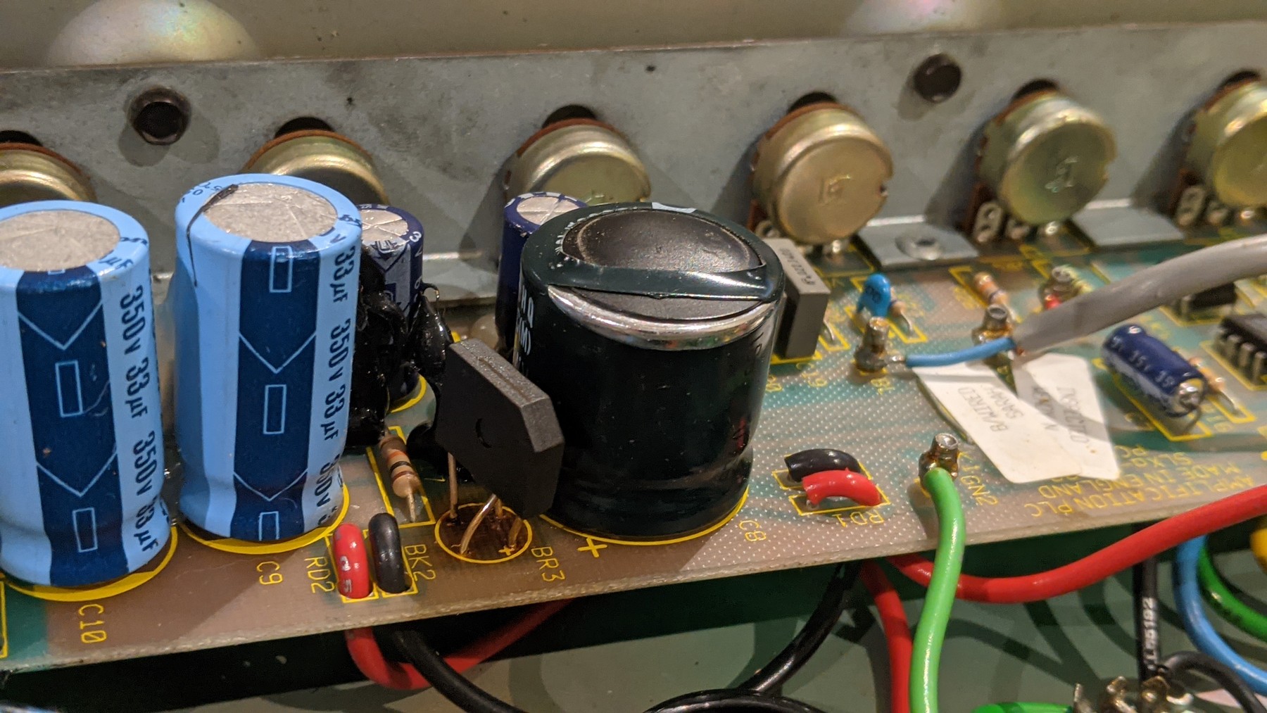
Below is an image of what not to do… Notice the replaced BR3 rectifier but the heat still takes out C8 and it doesn’t address the damage on the underside of the PCB.
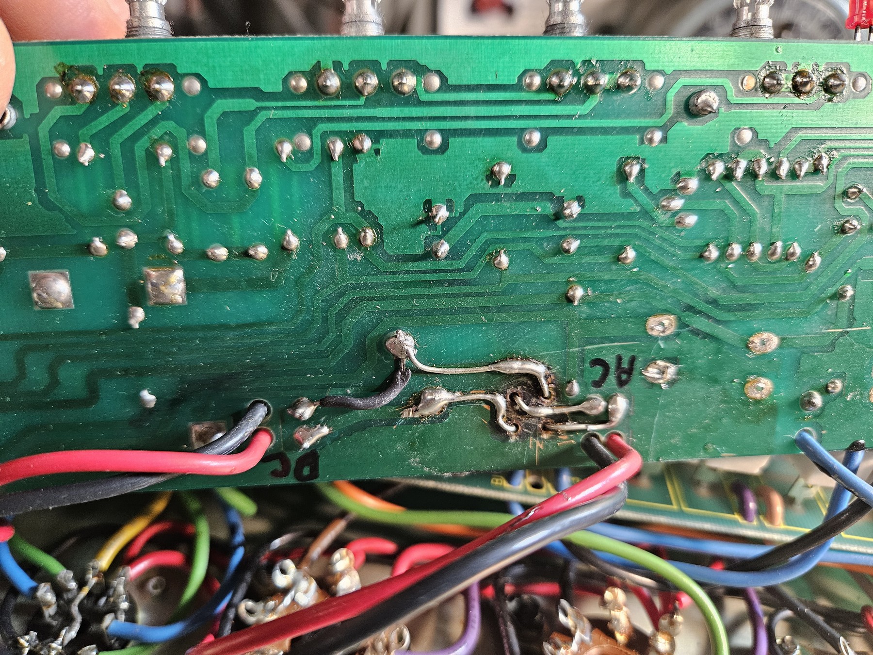
The next image below shows another example of what not to do. The leads were extended to circumvent the damaged traces but the carbon in the burnt PCB can become conductive leading to other problems. This is why we abandon this altogether.
The next image below is an unmolested SL-X. We will start by removing C8, BR3, and both sets of red and black wires from the board. These wires terminate on V4 and V3. Remove the wires from the tube heater pins as well.
Notice the dark area under where BR3 sits. It is much more apparent when looking at it up close.
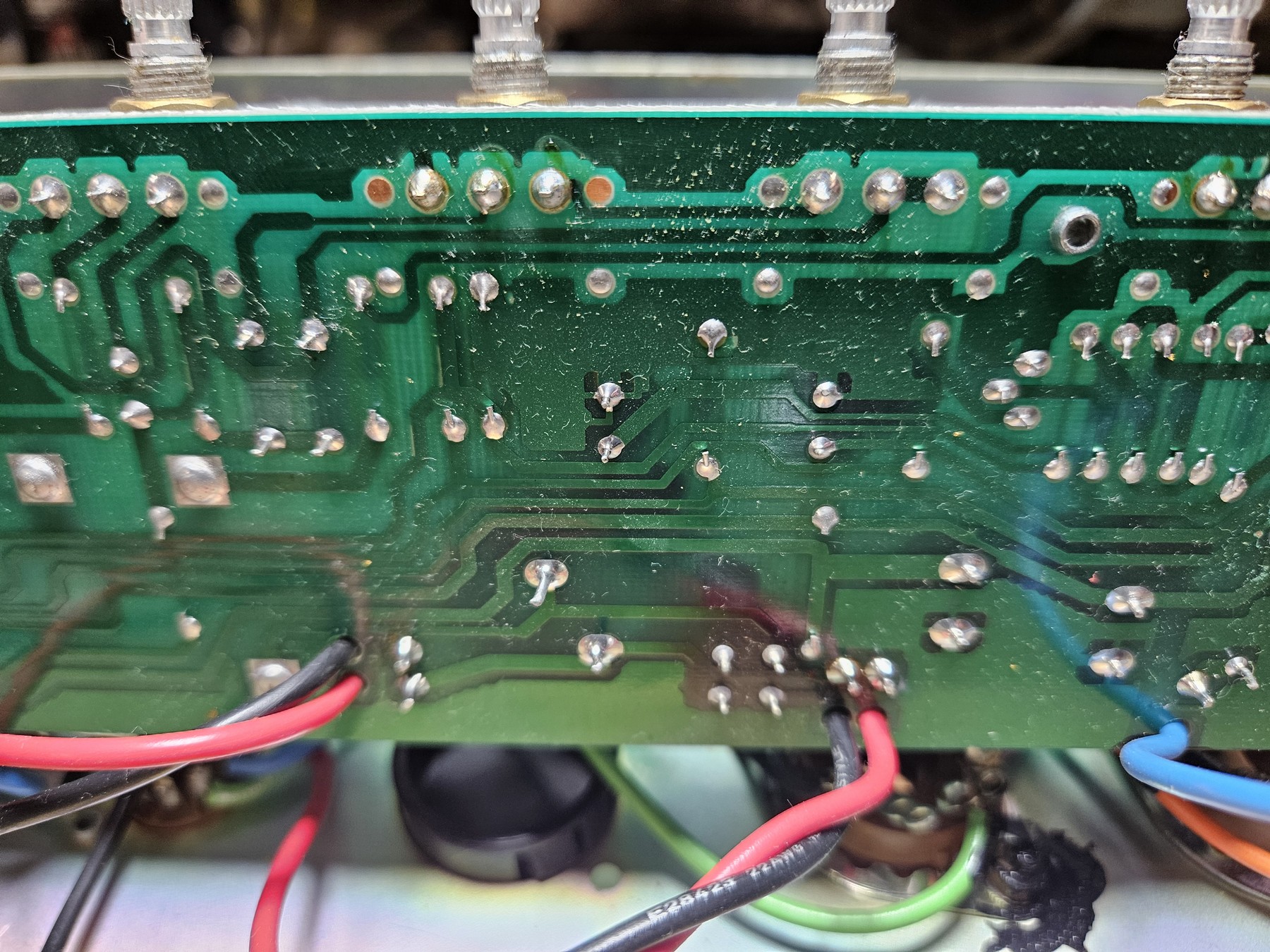
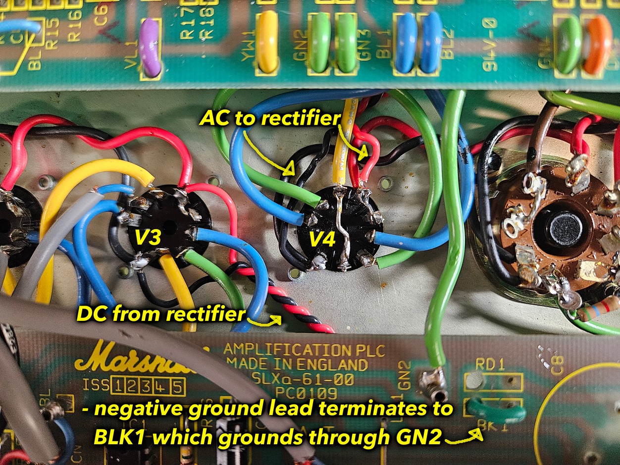
The incoming AC for the rectifier comes from the V4 phase inverter heater pins. You will need to add longer wire here to get to the new location of the circuit. I recommend using 20AWG teflon coated wire. Twist a new pair tightly and add them to the V4 heater pins where we just removed the existing wires.
Next we need a terminal strip. A five lug / 5th lug common terminal strip works perfect for this job. These can be purchased in packs of five from tubesandmore.com
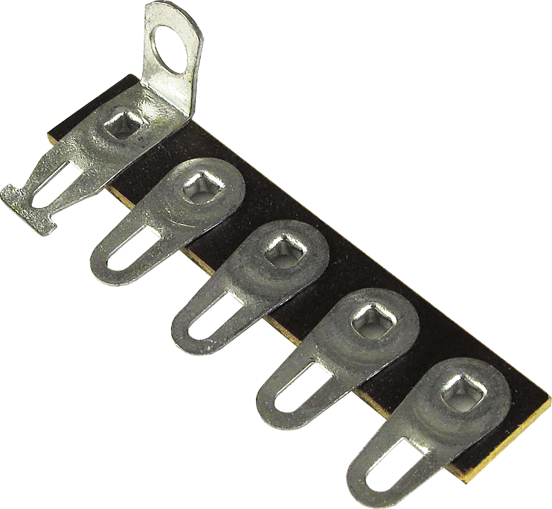
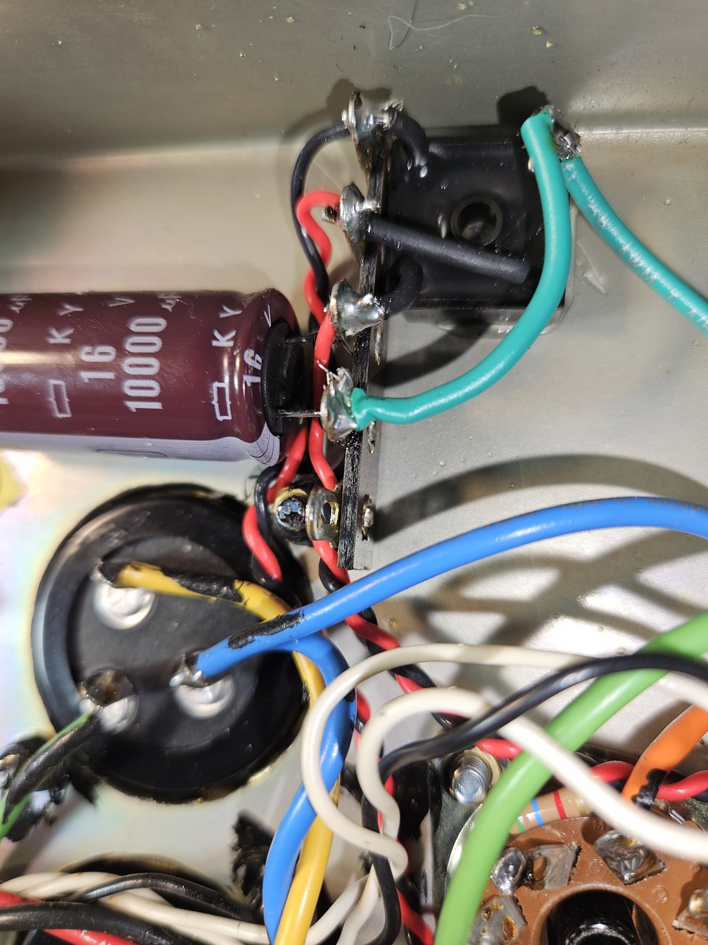
To avoid drilling any new holes in the chassis we can mount this strip using the mounting screw for the main filter cap. Below is an example of the finished job and a freshly recapped SL-X amplifier.
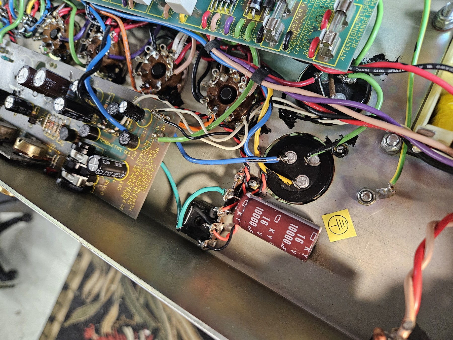
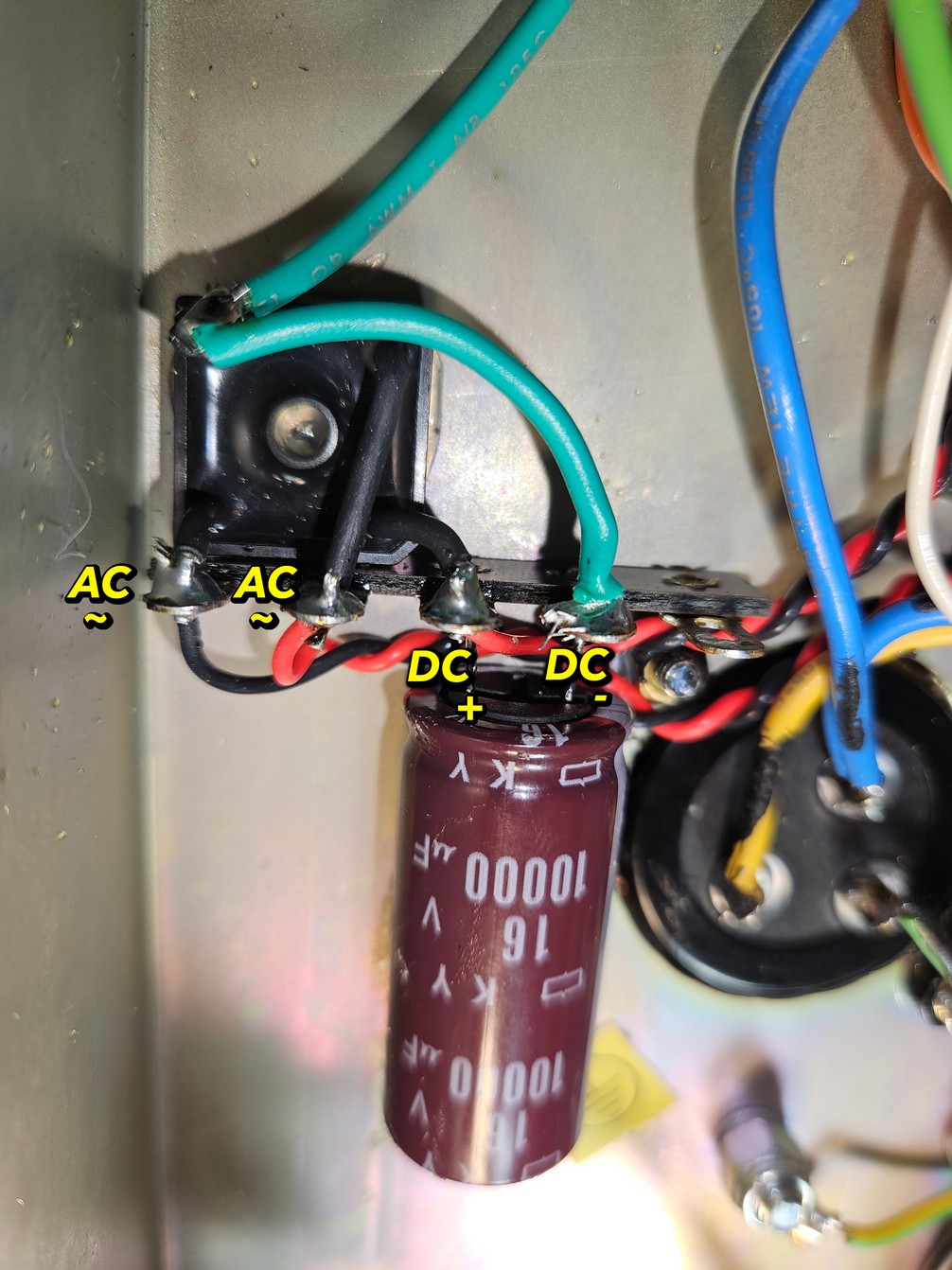
The AC leads from the rectifier tie to the outer two most lugs. The leads are insulated with heat shrink but that’s more for aesthetic purposes. The leads can be bent and have plenty of room so no unwanted contact occurs. You will terminate your incoming AC wires from the V4 heater pins to these same terminals. Orientation does not matter here.
Use RTV silicone sealant to affix the rectifier to the chassis. You could use the center hole to affix the rectifier to the chassis with a screw but I prefer not to drill whenever possible. RTV and the heavy leads soldered to the terminals will provide a stable base.
The + lead on the rectifier must tie to the same terminal as the + lead on the capacitor. Use RTV sealant to affix this capacitor to the chassis as well. The – negative lead on the capacitor must tie to the – negative terminal of the rectifier. This needs to be grounded and you can get away with just using the common terminal of the strip. I like to keep the stock grounding scheme so to do so we will run a new ground wire from the negative terminals to where the black wire going to V3 was removed from the PCB. This ties into a green wire marked GN2 on the board. Check for continuity.
Next you will need another pair of twisted wires to go from our terminal strip to the V3 heater pins. This new pair will connect to the positive and negative terminals we used to connect the capacitor and rectifier.
For lead dress, the AC wires should run along the existing AC heater wires under the rear board. The DC twisted pair can run under the front board without causing any noise issues. You can run these in any way you’d like really.
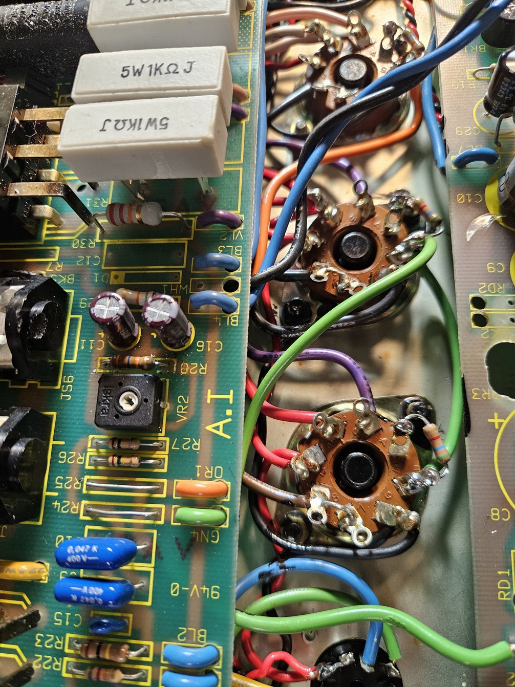
Next we move on to placing the grid stoppers on the tube sockets. Start by removing the green and orange wires from the output tube pins. On the rear board you also want to remove R24 and R25 and use a bus wire in their place. For our new grid stoppers we will use 5.6K resistors and place them between pins 6 and 5. Pin 6 is unused so we are simply using this as an anchor point for our resistor. Our input signal and negative voltage from the bias supply enters the tube through pin 5.
Once you have affixed your resistor, run the green and orange wires back to their respective tubes. Which tube is first doesn’t matter but do not mix up which pair of tubes the wires go to. If installed backwards the amp will oscillate heavily and it’s a very jarring sound when you don’t expect it! The wire will come from the board and tie to pin 6 of one tube then run a jumper wire from this same pin to pin 6 of the next tube of the corresponding pair. To save frustration, just clip the wire ends off and strip new ends. There should be enough slack in the wire to do this. The finished job should look like this. Notice the links for R24 and R25. In this image, the grid leak resistors R26 and R27 have yet to be changed from 150K to 220K.
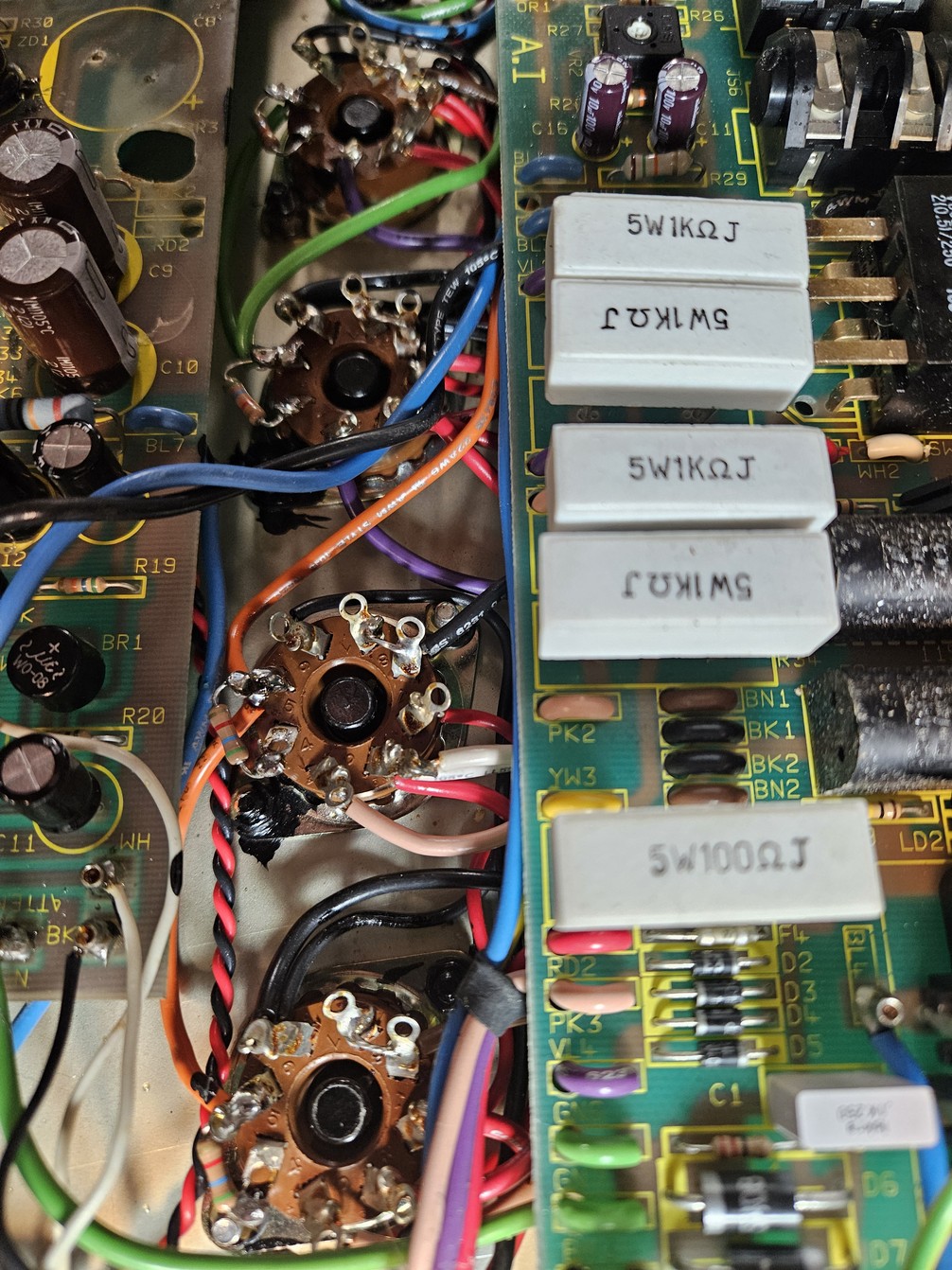
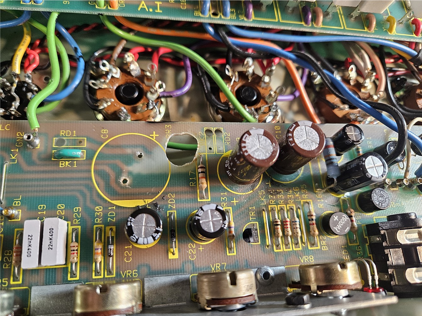
Well, that’s about it. Changing out the other components should be rather straightforward. Here’s another photo of the PCB with the burnt parts drilled out. It can get messy but it’s safer practice to remove anything that could conduct electricity where it’s unwanted. R17 is really the only resistor in close proximity to the damaged area. It really depends on how much heat damage has occurred on the board. When in doubt, drill it out.
Additional Notes
- We covered most of the important parts. Keep in mind the fragility of the PCB traces as you work. A soldering vacuum for parts removal makes the job go much faster and safer. It’s better to clip the component leads on the top side before attempting removal. It will be less stress on the traces. New capacitors will be much smaller than the ones that came out. They don’t need much to secure them in place. I use a small dab of RTV sealant under each capacitor prior to installation. Don’t use too much, if it pokes through the hole it will make soldering the component lead extremely difficult.
- In rare cases these amps can make excessive noise when no instrument is plugged in. If this is happening the noise can be mitigated by placing a 47pF ceramic disc capacitor across the switched contacts of the input jack underneath the board.
- It is common for wires to break when removing these boards for service. Don’t panic. Just keep good track of which wires have broken and ensure they are reconnected when your work is complete. Check over the amplifier thoroughly for other wires that may have broken that you didn’t see. I’ve seen them break right at the PCB and the wire is still secured through the hole.
- A final note on tone… These amps are capable of so much more. The easiest “mods” are to put an EQ in the FX loop and if you want even higher gain, hit the front end with a boost like a stock TS9 Tube Screamer. The EQ can boost much of the low end and the power section can easily handle it. This will make it seem like an entirely different beast. The magic of a pedal like the TS9 is that it cuts off a lot of low end in the guitar signal. It works well in a circuit like this as it allows the preamp gain control to be turned up even higher and the low end doesn’t flub out.
With the right settings these amps really can capture the classic Marshall rock and roll sounds as well as high gain death and black metal.
That’s it.
Schematics
Reference schematics — the Purgasound-drawn SL-X drawings, the factory 5881 conversion sheet, and the original Marshall preamp and power amp drawings. Click any drawing to enlarge it.
© Purgasound 2026 · www.purgasound.com