
Knowledge Hub
The Ultimate Split Channel JCM800 Guide!
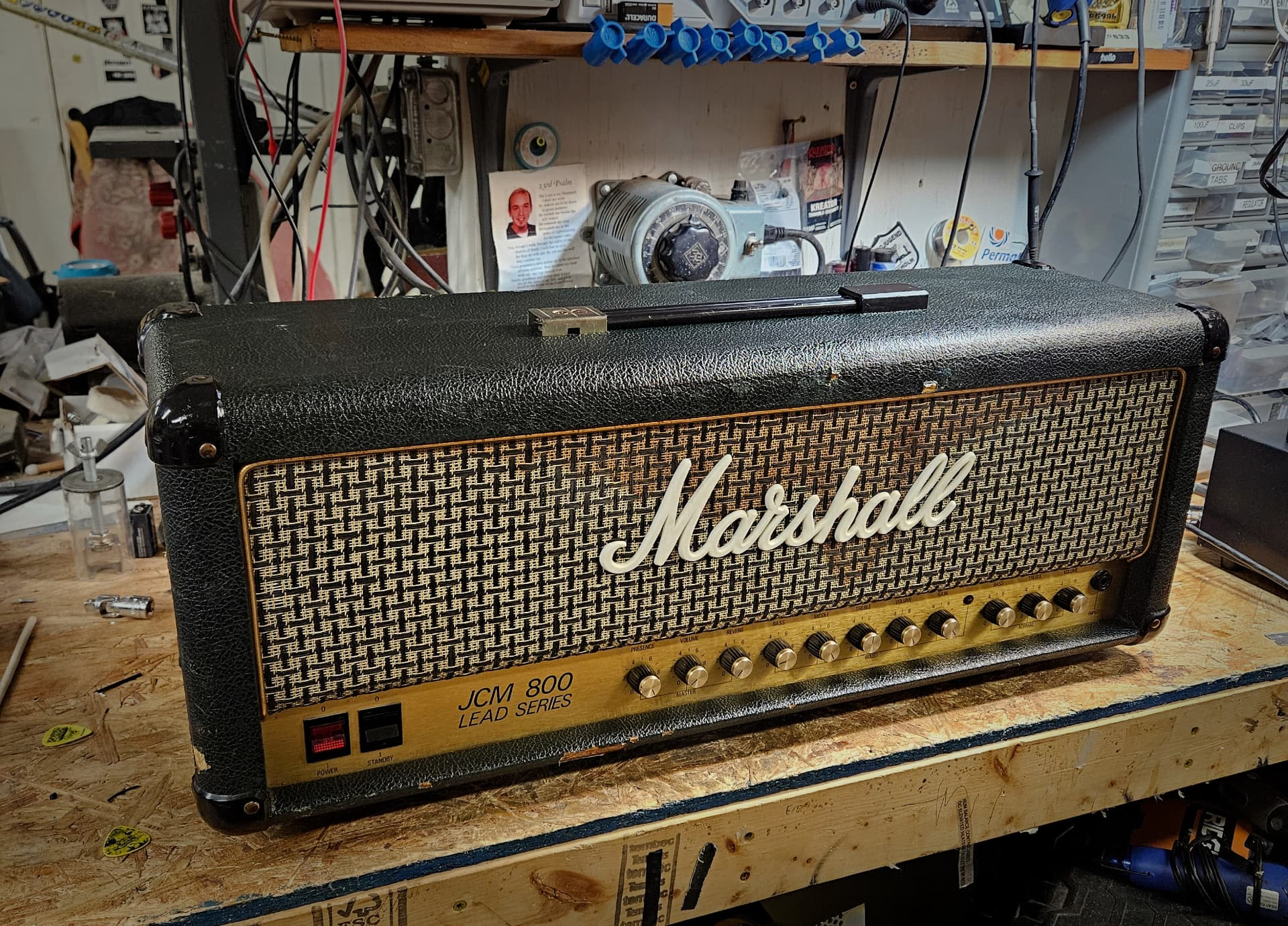
This guide is to address a few issues with the Split Channel JCM800 Series 2205 and 2210 models. Mainly we will be addressing the well known channel bleed issue as well as the oscillation problem that is present on earlier models. This may be applicable to combos as well but this has not been directly verified at the time this guide was authored.
The Split Channel JCM 800 Series amplifiers are among the most divisive in the lineup. Personally, I think they can sound great but can see where the bad rap comes from. First off, they're not a 2203! Second, they had multiple issues that were never truly corrected before the models were discontinued. The circuit had revisions that attempted to correct the channel bleed problem but never quite got it. This guide will show you how to fix that once and for all. Another issue is oscillation at high gain settings. The layout, bad grounding, and lack of shielding all play a significant role in how noisy these amplifiers are. Due to the PCB design we cannot correct layout issues but can provide a little improvement by adopting the latest grounding schemes and tube layout order and apply them to earlier models.
The circuits starting getting updates in the later part of the decade but by this time the amplifiers' reputation had been cemented and the 90's would mark the beginning of the company shifting towards their new sonic footprint starting with the JCM 900 series.
It would be too much of an undertaking to identify when exactly each fix was implemented so we will use the most up-to-date 2210/2205 from 1989 and apply our new fixes, along with Marshall's updates, and apply them to all previous years. Note that this guide only applies to models utilizing the CA3046 chip. The first Split Channel JCM 800 amplifiers have a slightly different preamp, master volume, and do not use the CA3046 chip for channel switching. We will start by taking a look at some examples from the mid 80's and can see some of the key differences. Later, the guide will provide step by step instructions on replacing all capacitors, refining the grounding scheme, and altering the preamp tube layout to the latest version. This way all the necessary work can be done at once and you may find your amplifier may already possess some of the changes.
Let's take a quick look at this 2205 from 1986 to see some obvious differences.
Download the 1986 2205 schematic showing the capacitors missing from the PCB (PDF)
So instead of going down the rabbit hole and comparing each, let's start going step by step to get everything updated.
- Step 1: Remove wire from footswitch jack sleeve terminal to DI or speaker output jack sleeve terminal.
- Step 2: Add ground lug to chassis under footswitch jack.
Note
Older models will have a ground wire from the footswitch jack sleeve connected to the speaker output jack sleeves. Disconnect the wire end from the speaker outputs and terminate to a ground lug on the chassis beneath the jack. This ground lug may not be present so you can add this if needed.
- Step 3: Add 22uF and 100uF caps on footswitch jack and terminate to new ground lug.
- Step 4: Remove wire from ground lug at reverb transformer bolt.
- Step 5: Connect new wire from reverb transformer ground lug to FX loop jack sleeve terminal.
- Step 6: Connect new wire from black reverb wire shield terminal on reverb transformer to connection point on PCB beside C18 — will have to flip board to make connection.
Note on Reverb Wire Shielding
The reverb send wire and one end of the reverb transformer tap may be tied to the ground lug on the chassis beside the transformer. Updated grounding requires removal of the connection to the ground lug and a new wire should be installed from the transformer tap/wire shield and fitted to the hole in the PCB beside C18. This connects the transformer/wire shield to the 0V plane on the PCB.
- Step 7: Remove knobs, remove pot nuts with ½" socket, flip board.
- Step 8: Replace C35 and C36 10uF 100V bias capacitors with 10uF 160V caps.
- Step 9: Replace C28 — 22uF 25V.
- Step 10: Replace C18 — 22uF 25V.
- Step 11: Add ground wire from reverb transformer top terminal to connection point on PCB beside the negative end of C18.
- Step 12: Remove C38 0.22uF 100V capacitor on the top side of the board.
Note
C38 is changed on later schematic versions to C40 and the end connected to the treble wiper is now connected to the wiper of the clean channel volume pot. C40 is mounted on the underside of the PCB as a 0.22uF yellow tantalum capacitor and should be increased to 22uF. If a polarized capacitor is used then connect negative end to CA4036 pin and positive end to volume control wiper. See Step 17.
- Step 13: Replace C10 — 22uF 25V.
- Step 14: Replace C9 — 3300uF 6.3V — increase voltage rating to 10V.
- Step 15: Remove the 10K/1uF resistor/capacitor between the + side of D5 and the LINK/BK junction.
- Step 16: Remove ground bus wire and connecting wire between back of clean channel pots and BK on board beside input jack. Without this black wire this amp will not work unless Step 5 has been completed. The PCB ground plane for the preamp travels through the wire shield feeding the FX loop jacks which are now grounded to the lug at the reverb transformer bolt.
- Step 17: Install C40, C41 and C42 on the underside of the PCB as shown. Schematic shows 10uF capacitors for C41 and C42. Increase value to 22uF or 25uF for all three.
- Step 18: Swap wiring for V3A (pins 6, 7, 8) and V4B (pins 1, 2, 3). You will need to verify the wiring prior to moving things around.
Note
Schematic shows incorrectly reversed labels on all triodes. For example, pin 2 of a 12AX7 is the grid of the second triode referred to as VB. The schematic shows the instrument input labeled as the V1A grid which would be pin 7 but they have this wired to pin 2 which would actually be V1B. When referring to 12AX7 pinouts, this guide will use correct terminology and always refer to pins 1, 2, and 3 as VB and 6, 7, 8 as VA respectively.
- Step 19: Add C48 if missing, which is a 47pF capacitor across pins 2 and 3 of V3. Confirm correct wiring as the VR5 Volume control wiper should connect directly to the grid (pin 2) of V3B.
- Step 20: Effects loop jack sleeve terminals should be grounded to chassis ground lug located on the reverb transformer mounting bolt.
Note: FX Loop Jacks
Schematic shows ground from jack sleeve terminals going to “C” on schematic which is the ground plane on the front PCB. However, I've never seen this to be the case in reality. In these mid 80's models, the signal wires to the FX loop jacks are run with shielded cable. The shield is tied to the jack sleeve at one end and the PCB ground plane on the other, thus the shield is carrying the ground. However... to update the grounding to the latest drawing revision you must add a ground wire from the jack sleeve to the chassis ground lug beside the reverb transformer. Does this create ground loops? Yeah, probably. They are everywhere on these amps.
2210 Preamp Schematic
The 2210 preamp schematic with corrected tube labels and the highlighted parts (C40, C41, C42) to change to 25uF 25V.
That pretty much concludes the main fixes for channel bleed and oscillation. There are still ground loops present all over the place and it's very possible there is a much more quiet application out there. At a certain point comes diminishing returns as you may be able to improve the grounding but it would not improve the overall layout which is another source of unwanted noise. I think these fixes get the amp to a much more usable state and you could always use a noise gate in the effects loop to knock off the unwanted high gain hiss.
I started writing this guide sometime last year and never got around to finishing it. I'm going to go ahead and publish what I have so far as of October 2026 as it's been sitting too long. There are some other tips and tricks I'd like to add to this document at some point and by that time I'll make the whole thing downloadable as a single PDF.
Until then, I hope you find this useful.
© Purgasound 2026 · www.purgasound.com